

Clash detection is the process of finding physical or functional conflicts between building systems, such as structural, architectural, mechanical, electrical and plumbing (MEP), before construction begins. In BIM, software compares the discipline models, flags every place two elements intersect or violate a required clearance, and reports each one so the team can fix it in the model instead of on site.
A structural beam sitting exactly where a sprinkler main needs to run. A duct that only fits if the electrical conduit wasn’t already there. On a busy project, these conflicts used to surface on site, usually with a crew standing around while someone reworked the drawings by hand. That’s the problem model coordination was built to solve, and even with BIM now standard practice, it’s still one of the most argued-about parts of the job: how much of it should be automated, who should own the process, and what actually counts as “resolved.
This guide covers what it is, how it differs in BIM and in construction generally, the three types of clashes, the workflow from federated model to verified fix, clash matrices and tolerances, the standards behind coordination, the main software options, and how software differs from outsourced services. It also shows where the KLASH BIM plugin from VAVETEK AI fits in that workflow.
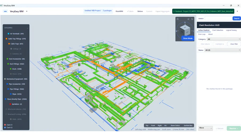
What Is Clash Detection?
It is the process of identifying physical or functional conflicts between building systems, structural, architectural, mechanical, electrical, and plumbing, before construction begins. Instead of discovering that a duct and a beam occupy the same physical space once a crew is standing in the room, coordination teams find that conflict inside a 3D model, where fixing it costs a few clicks rather than a change order.
At its core, it’s a comparison problem. Every discipline builds its own model, independently, on its own timeline: structural engineers model the frame, MEP engineers model ductwork and piping, architects model the envelope and partitions. Historically, multidisciplinary coordination relied heavily on 2D drawings, overlays, and manual reviews, making conflicts more difficult to identify before construction than they are in today’s federated BIM workflows. Software now overlays these models and flags every point where two elements physically intersect, or come closer than a required clearance allows.
What Is Clash Detection in BIM?
In BIM, the same comparison runs inside a Building Information Modeling environment, where every system exists as coordinated 3D geometry carrying real metadata rather than flat 2D lines. Because BIM models know the actual dimensions, position, and type of every pipe, duct, and beam, software can check thousands of intersections automatically instead of an engineer manually comparing drawing sets sheet by sheet.
This is what most people mean today when they talk about clash checking, and it’s the foundation that coordination software and outsourced services are both built around. A federated BIM model, meaning all discipline models combined into one coordinated view, is what makes automated checks possible in the first place. Without it, you’re back to overlays and guesswork.
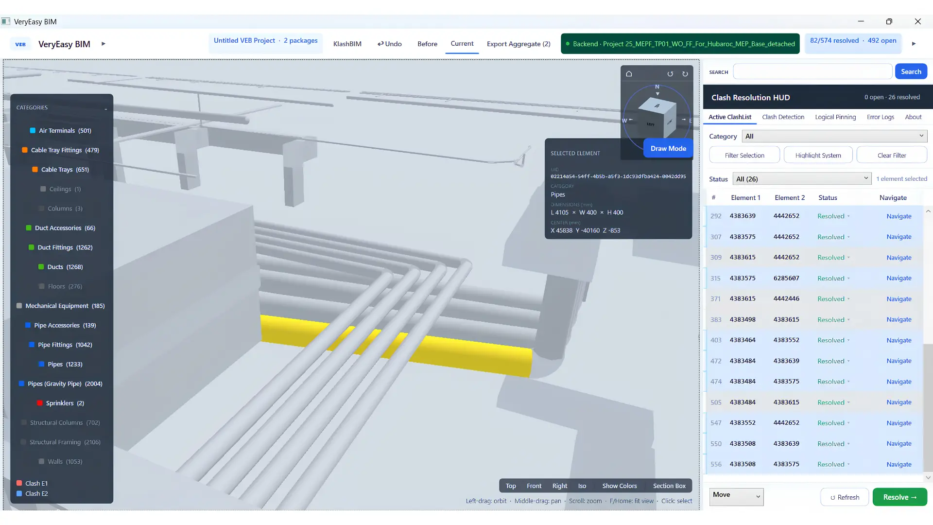
What Is Clash Detection in Construction?
In construction, the practice is broader: catching these conflicts across the entire project lifecycle, not just during design. It includes the BIM-based checks run before ground is broken, but it also covers the coordination meetings, RFIs, and field verifications that happen once trades are actually installing work.
A conflict caught in the model during design review is cheap: someone reroutes a duct in the software and moves on. The same conflict caught on site, after concrete has cured or ductwork has been fabricated and hung, is a change order, a schedule delay, and sometimes a safety issue if the fix has to happen around live utilities.
Reality capture belongs here too on renovation work. Laser scanning an existing building and comparing the as-built point cloud against a new design model is its own form of conflict checking, one that catches problems no drawing set was ever going to reveal because the drawings were wrong to begin with.
Why Clash Detection Matters
Rework is one of the most persistent cost drains in construction. The FMI and PlanGrid Construction Disconnected report, as summarized by Autodesk, estimated $31.3 billion in rework in the U.S. in 2018, and attributed 48% of all rework to poor project data and miscommunication. That study is a few years old and covers the U.S. only, but it shows the pattern: a large share of rework starts with information that didn’t reach the people who needed it.
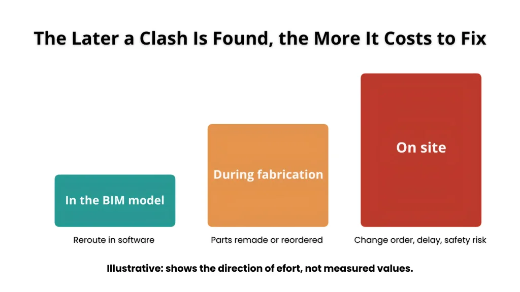
Beyond direct rework, unresolved clashes push back schedules, strain relationships between trades who each think the other side should have caught it, and in the worst cases compromise structural integrity or life-safety systems like fire suppression and egress. There is a quieter cost too: material waste. A duct fabricated to the wrong dimensions because it was rerouted after the fact costs labor hours and ends up in a dumpster.
This is where early model coordination becomes valuable. An Autodesk Digital Builder article on AECOM’s model-coordination workflow describes what happens without it: unexpected design changes and unnecessary rework, resulting in budget overruns and schedule delays. The same article stresses running coordination checks early, rather than late in design or on the construction site.
In practical terms, early checking moves coordination problems upstream, where they are generally easier to identify, discuss, and resolve, rather than leaving the project team to discover them after installation has begun.
Types of Clashes in BIM
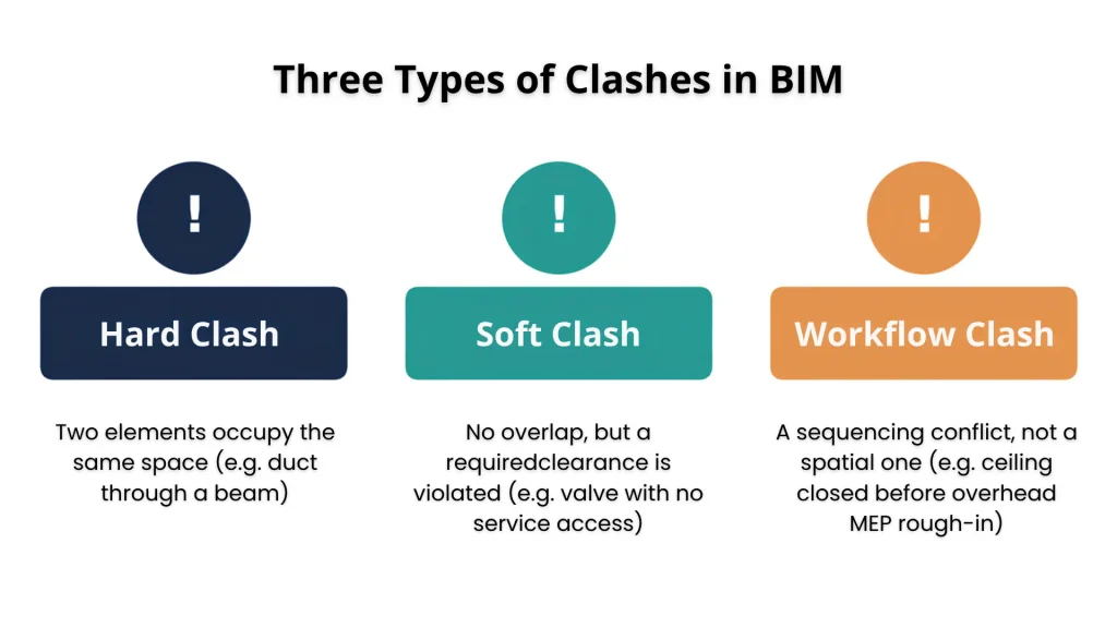
Not every clash looks the same, and treating them all identically slows a coordination process down. Most teams sort clashes into three categories, a split that Autodesk’s quick guide to BIM clashes also uses.
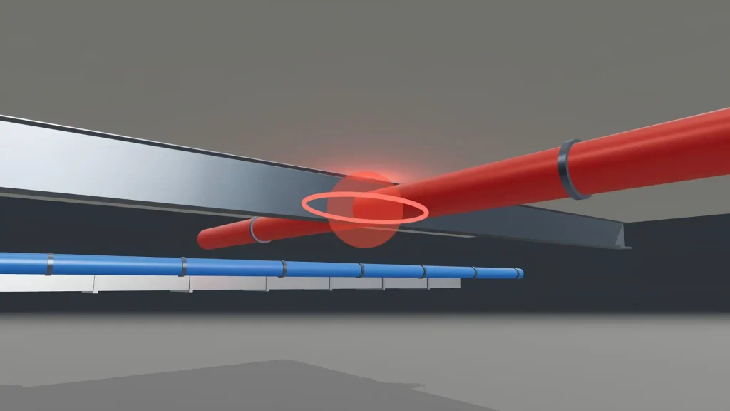
Hard Clashes
Two solid elements physically occupy the same space, like a pipe running straight through a structural beam, or two ducts overlapping in the same ceiling void. These are unambiguous and almost always need fixing before the model moves forward. For examples and resolution approaches, see our deeper guide to hard clashes in BIM.
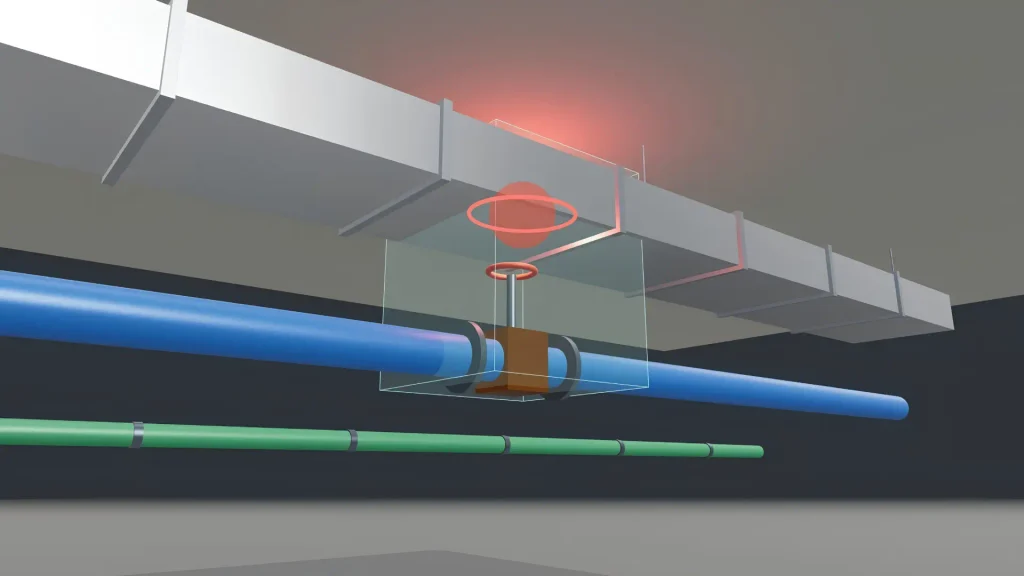
Soft (Clearance) Clashes
Soft clashes, also called clearance clashes, happen when elements don’t overlap but violate a required buffer. A valve that technically fits but leaves no room for a technician to service it later is a soft clash, and so is equipment placed too close to a fire-rated wall. These are often judgment calls rather than automatic fails, which is why rule setup, defining what clearance actually matters, is such an important step.
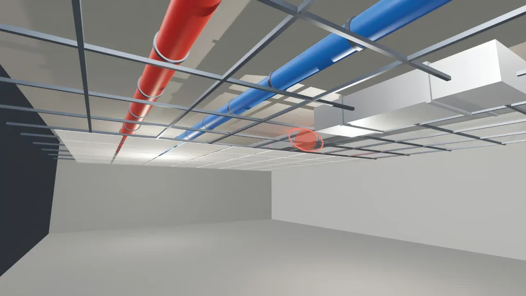
Workflow (4D) Clashes
Workflow clashes, sometimes called 4D or sequencing clashes, are timing conflicts rather than spatial ones. Nothing overlaps in the model, but the schedule has ceilings being closed in before overhead MEP rough-in and inspection are finished, which means the ceiling crew will have to open up finished work to let the MEP trades back in. A large air handling unit that can’t be moved into its plant room once the surrounding walls are closed is another classic case. These never show up in a standard spatial scan; they need the schedule checked against the installation sequence.
| Clash type | What it means | Typical example | Urgency |
|---|---|---|---|
| Hard clash | Two elements physically overlap | Duct running through a beam | Fix immediately |
| Soft clash | No overlap, but required clearance is violated | Valve with no maintenance access | Fix before construction |
| Workflow clash | Timing conflict in the installation sequence | Ceiling closed before MEP rough-in | Resolve in scheduling review |
How Does Clash Detection Work in BIM?
Most BIM clash checking follows a similar sequence, whether it’s run manually in a general coordination tool or automated through a dedicated platform.
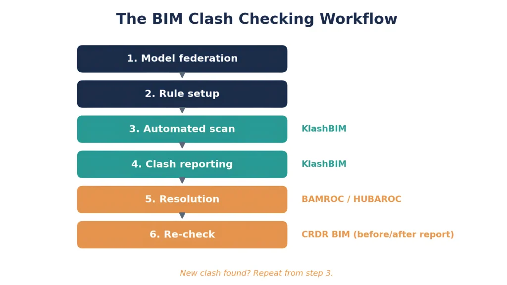
Model federation
Individual discipline models are linked together using a shared coordinate system so nothing shifts when it’s brought together. Agree levels, grids, units and naming before the first upload.
Rule setup
Teams define what counts as a clash for this project, including clearance tolerances and which element categories are checked against each other. A structural column and an architectural finish aren’t usually worth flagging; a column and a duct almost always are.
Automated scan
The software analyzes the relevant model elements against the predefined rules and identifies intersections or clearance violations automatically. A scan that would take a person days by eye takes minutes.
Clash reporting
Results are grouped by discipline, location, or severity, and assigned to whoever is responsible. A useful report tells an engineer exactly where to look, not just that “347 collisions were found.”
Resolution
Engineers move, resize, or reroute elements to eliminate the conflict, ideally without creating a new one elsewhere.
Re-check
The model is scanned again to confirm the fix worked and didn’t introduce a second clash three feet away.
The last step gets skipped more often than it should, usually because of time pressure late in a coordination cycle. Moving a duct to clear one clash can easily create another further along its run, which is a big part of why resolution, not finding clashes, has traditionally been the slowest and most error-prone part of the process.
Clash Matrix and Tolerances
Rule setup is where most of the quality in a coordination process comes from. The usual tool is a clash matrix: a grid that lists which discipline or system is tested against which, and with what tolerance. Testing everything against everything produces thousands of noise results. A matrix keeps each test meaningful, and keeps results assignable to a single responsible team.
The values below are illustrative starting points only. Each project should set its own in the BIM Execution Plan, based on the specification, local code and the fabricator’s needs.
| Test (A vs. B) | Clash type | Example tolerance | Notes |
|---|---|---|---|
| Ductwork vs. structure | Hard | 0 mm | Check beam web openings against approved penetrations |
| Piping vs. structure | Hard + soft | 0 mm hard; insulation thickness as soft buffer | Model insulation, or add its thickness to the tolerance |
| Duct vs. pipe | Hard + soft | 0 mm hard; 25–50 mm soft | Allow for hangers and supports |
| MEP vs. MEP | Hard | 0 mm | Run inside one trade first, then between trades |
| Equipment vs. service zone | Soft | Per manufacturer or code | Filter pull, valve access, electrical working space (e.g. NEC 110.26 in the U.S.) |
| MEP vs. fire-rated wall | Soft | Per fire strategy | Penetrations need a fire-stopping detail |
Two habits keep a matrix useful. First, group related results so one root cause shows as one issue, not forty. Second, filter false positives, such as elements that intersect by design (a pipe passing through a sleeve), so the team spends its time on real conflicts.
Who Moves First? Routing Priority
When two systems clash, someone has to move. Without an agreed order, every trade waits for another or resolves it in a way that breaks their neighbor’s route. A common priority rule is that the element that is hardest to reroute keeps its position, and more flexible systems move around it:
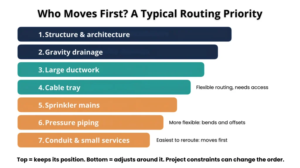
- Structure and architecture (fixed unless the design team approves a change)
- Gravity drainage (needs continuous fall, so it has the least freedom)
- Large ductwork
- Cable tray
- Sprinkler mains
- Pressure piping
- Conduit and small services (easiest to reroute)
Treat this as a starting point. Project constraints, such as a fixed ceiling height or a fire-rated shaft, can change the order. The important thing is to write the agreed order down in the BIM Execution Plan so each coordinator knows who adjusts first.
Manual vs. Automated Clash Checking
It’s worth being specific about what “automated” actually replaced. Before federated BIM models were standard, coordination meant printing drawing sets from every discipline and overlaying them, first physically on a light table, later digitally by stacking PDFs, then scanning each sheet by eye for anything that looked like it overlapped.
This worked for conflicts that were visually obvious on a 2D plan. It missed almost everything that only showed up in section or elevation, and it depended entirely on how carefully one person looked at a given sheet on a given day. A duct running three feet lower than shown on the reflected ceiling plan, but correct in section, could sail through review undetected for months.
Finding geometric intersections between model elements is now a mature capability in BIM software. The more complex challenge is resolution: determining a practical, constructible fix without creating new conflicts elsewhere. That is why the next generation of tools is focused on the step after the scan.
Standards and Formats Behind Coordination
A few shared standards keep multi-company coordination from turning into a file-format argument.
IFC (Industry Foundation Classes)
The open model format from buildingSMART, used to exchange geometry and data between different BIM tools.
BCF (BIM Collaboration Format)
An openBIM standard for passing model-based issues between applications. According to buildingSMART, it carries the issue as XML that references the IFC model and identifies elements by their IFC GUIDs, with a captured view as an image. It is widely used to track clashes as assignable issues.
ISO 19650
The international standard series for managing information over the life of a built asset, including how project information is exchanged and organized in a common data environment. See the ISO 19650-1 standard.
LOD (Level of Development)
Defines how detailed and reliable an element is at each stage. A clash check is only as trustworthy as the detail in the models being checked.
Who Owns Clash Coordination on a Project?
Ownership varies, but the roles are fairly consistent. A BIM manager or coordinator runs the federated model and the scans. Discipline leads (structural, architectural, MEP) resolve the clashes assigned to them. On many contractor-led jobs, a VDC or MEP coordinator drives the weekly MEP coordination meeting. The project manager and scheduler need a seat for workflow clashes. Whoever owns it, the clash matrix, the tolerances and the issue-tracking method should be agreed in writing at the start.
Clash Detection Software: Tools to Know
The tools range from general coordination platforms to purpose-built plugins. The names below are the ones coordinators most often mention. Check each vendor’s current documentation for exact features.
Autodesk Navisworks
A long-standing model-aggregation and coordination tool with a built-in clash module.
Autodesk Construction Cloud (Model Coordination)
Cloud-based coordination that finds clashes across uploaded models and tracks issues.
Solibri
Model checking software that includes clash checks alongside rule-based quality checks.
Revizto
Coordination and issue tracking with clash checking and a shared viewer.
BIMcollab
Issue management built around BCF, used to track and assign coordination issues.
KLASH BIM
A plugin for MEP and structural elements, covered in the next section.
KLASH BIM: MEP and Structural Clash Checking
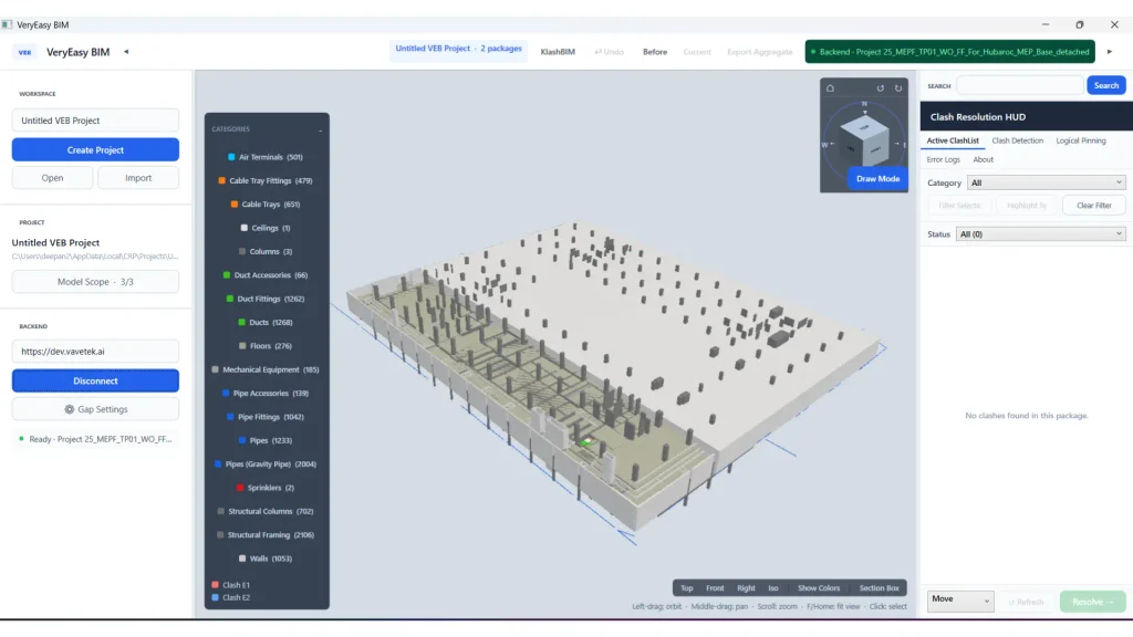
KLASH BIM (product page) is a BIM clash detection plugin developed by VAVETEK AI for identifying and managing clashes between MEP and structural elements in BIM models. It automates checks between mechanical, electrical, plumbing and structural elements, generates customizable documentation reports, and integrates with the company’s automatic resolver for AI-powered clash resolution. It is designed to fit into existing BIM workflows.
Where it fits in the workflow
It covers the scan and reporting steps described earlier: it finds the MEP and structural clashes in the model and produces documentation reports that can be customized to the project. That gives the coordination team a clean, structured starting point for assigning and resolving issues, instead of a raw list of collisions.
Who it is built for
The plugin is aimed at BIM coordinators, MEP coordinators, MEP and structural engineers, general contractors and EPC contractors. It is a fit for teams that run coordination in-house and want detection tied directly to resolution, rather than moving clash data between unrelated tools.
Clash Detection Software vs. Services
These two terms get used interchangeably, but they describe different arrangements for who actually does the work.
Software is a tool your own team runs, whether that’s a general BIM coordination platform or something purpose-built for finding and resolving clashes. Your team owns the models, sets the rules, runs the scans, and manages the resolution workflow. The tradeoff is that someone in-house needs to actually know how to run it well.
Services, including BIM coordination services offered by outside firms, hand some or all of that process to a third-party team who runs the scans, produces the reports, and sometimes manages 1resolution on your behalf. See our overview of MEP clash resolution services for how a full-lifecycle service works.
| In-house software | Outsourced services | |
|---|---|---|
| Who runs it | Your own team | A third-party coordination firm |
| Models and workflow | Stay in-house | Held by the provider until handoff |
| Best fit | Teams running similar projects repeatedly | One-off or unusually complex builds |
| Staffing | Needs a trained BIM coordinator | Minimal in-house BIM staffing needed |
| Speed to start | Immediate, if staff already know the tool | Depends on the provider’s onboarding and turnaround |
Neither option is inherently better. A firm running dozens of similar projects a year usually gets more long-term value from building software expertise in-house, since the tool pays for itself across many jobs. A team handling one complex build with systems it doesn’t have deep experience with often gets more from a service that already has the process, and the judgment calls it requires, dialed in.
What services typically include
Scope varies, but services usually cover some combination of federating discipline models, setting up and maintaining clash rules, running scheduled scans, producing prioritized reports, facilitating the coordination meeting, and tracking resolved versus outstanding clashes. Some providers stop at reporting and leave resolution to the design team; others take resolution on as part of the engagement. Clarify that boundary before signing a scope of work, since finding clashes and resolving them aren’t automatically the same line item.
Common Mistakes in Clash Checking
1. Testing everything against everything
Without a clash matrix, results drown in noise.
2. No agreed routing priority
Trades wait on each other, or move in ways that create new clashes.
3. Skipping the re-check
A fix in one place is a potential clash in another.
4. Unreliable models
Wrong coordinates, missing insulation, or inconsistent LOD produce false results and false confidence.
5. Treating every clash as equal
Hard, soft and workflow clashes need different owners and different timelines.
6. Tracking issues in screenshots and email
Use an issue format such as BCF so each clash has an owner, status and history.
7. Confusing finding with fixing
Reporting 347 clashes is not progress until someone has resolved them and verified the fix.
How to Choose an Approach
Before picking a direction, ask a few practical questions. How many disciplines are actually clashing on this project, and how complex are the MEP systems involved? Does the in-house team have bandwidth to run coordination meetings on top of everything else on their plate? Is the real goal just finding clashes, or does resolution also need to move faster, since that’s usually where the time gets spent?
For teams that want control without doing everything by hand, a hybrid approach works well: a plugin such as KLASH BIM for scanning and reporting, paired with automatic resolution for high-volume clashes and guided resolution where an engineer needs to make the call.
Conclusion
Clash detection has become a fundamental part of BIM coordination because identifying conflicts before construction is faster, safer, and more economical than resolving them after installation begins. As BIM workflows evolve, the focus is also moving beyond simply finding clashes toward resolving them more efficiently.
VAVETEK AI builds tools across this workflow: KLASH BIM for MEP and structural scanning, BAMROC for automatic resolution, HUBAROC for human-assisted resolution, and CRDR BIM for before-and-after reporting.
Want to see KLASH BIM on your own BIM models? Request a demo and the VAVETEK AI team will walk you through it.
Frequently Asked Questions (FAQ’s)
1. What is clash detection?
It is the process of finding physical or functional conflicts between building systems, such as structural, architectural and MEP, before construction begins. It is usually done by comparing 3D models, so conflicts are fixed in the model instead of being discovered on site, where they cost far more to correct.
2. What is clash detection in BIM?
It is the same comparison run inside a federated Building Information Model, where every discipline’s model carries real geometry and metadata. Software then checks thousands of potential conflicts automatically against rules and tolerances, instead of a person comparing drawings by hand.
3. How does the construction version differ from the BIM version?
It is the wider practice across the whole project: the BIM-based checks done before construction starts, plus the RFIs, field verification and as-built comparisons that happen once trades are on site. The BIM version is one part of it.
4. What are the types of clashes?
There are three. Hard clashes are physical overlaps, such as a duct through a beam. Soft clashes are clearance violations, such as a valve with no service access. Workflow clashes are sequencing conflicts, such as a ceiling closed before overhead MEP rough-in is complete.
5. What is a clash matrix?
A clash matrix is a grid that defines which disciplines or systems are tested against each other and with what tolerance. It keeps each test meaningful, cuts false positives, and makes every result assignable to one responsible team.
6. What is the difference between software and outsourced services?
Software is a tool your own team runs and owns. Services hand some or all of the process, such as scans, reports and sometimes resolution, to an outside team. Services suit projects without dedicated in-house BIM coordination staff.
7. Is it worth using software on a small project?
It depends more on system complexity than size. A small building with simple MEP routing may not need much beyond a basic overlay check. A small but mechanically dense project, such as a lab or hospital wing, usually benefits from the same rigor a larger one would use